Chapter 2 : 2D Drawing basics tools
In this lesson, you will learn to use the basic drawing tools as follows
1) To draw Points, Lines, Rectangles, Circles, Ellipses, Arcs, Polygons, Polylines and Hatch tools.
2) To use the Erase, Undo and Redo tools.
3) Draw entities using the absolute coordinate points.
4) Draw entities using the relative coordinate points.
5) Draw entities using the tracking method.
6) Turn OFF the Dynamic Input icon. You will learn about Dynamic Input later in this chapter.
7) To draw a point, click Home > Draw >Multiple Points
on the ribbon,or enter POINT in the command line.
8) Type 50,50 and press ENTER.
9) Type DDPTYPE and press ENTER.

you will have a pop-up for Point style and size, choose
Point Style as per you wish but most probably people prefer + or x style.
Point size - choose Set Size Relative to Screen and enter 5 at Point Size input option.
10) Click Save on the Quick Access Toolbar.
11) Save as Point-example.dwg.
1) Start AutoCAD.
2) Click Start Drawing > Templates > acadISO-Named PlotStyles.dwt .
3) Click Zoom > Zoom All on the Navigation Bar.
4) Turn OFF the Grid Display .
5) Turn OFF the Dynamic Input .
6) To draw a point, click Home > Draw >Line
on the ribbon,or enter LINE or L in the command line.
7) Type 100,100 and press ENTER . This defines the first point of the line.
8) Type 200,100 and press ENTER .
9) Type 200,150 and press ENTER .
10) Type 100,150 and press ENTER .
11) Select the Close option from the command line.This creates a rectangle as shown below.
12) Click Save on the Quick Access Toolbar.
13) Save as Line-Ex1.dwg .
14) Close file.
In the polar coordinate system, you define the location of a point by entering two values: distance from the previous point and angle from the zero degrees. You enter the distance value along with the '@' symbol and angle value with the '< 'symbol. You have to make a note that AutoCAD measures the angle in anti-clockwise direction.
1) Start AutoCAD.
2) Click Start Drawing > Templates > acadISO-Named PlotStyles.dwt .
3) Click Zoom > Zoom All on the Navigation Bar.
4) Turn OFF the Grid Display .
5) Turn OFF the Dynamic Input .
6) To draw a point, click Home > Draw >Line on the ribbon,or enter LINE or L in the command line.
7) Type 100,100 and press ENTER . This defines the first point of the line.
8) Type @100<0 and press ENTER .
9) Type @50<90 and press ENTER.
10) Type @100<180 and press ENTER.
11) Select the Close option from the command line.
12 ) Save file and close.
1) To draw Points, Lines, Rectangles, Circles, Ellipses, Arcs, Polygons, Polylines and Hatch tools.
2) To use the Erase, Undo and Redo tools.
3) Draw entities using the absolute coordinate points.
4) Draw entities using the relative coordinate points.
5) Draw entities using the tracking method.
POINT
This command used to specify a point.You can specify a full three-dimensional location for a point. You can control the appearance of point objects by using DDPTYPE command.DDPTYPE
Specifies the display style and size (Relative to screen or absolute units) of point objects.
Example :
In this example, you will create point object by specifying point in the absolute coordinate system.
1) Start AutoCAD
2) On the Welcome screen, click Start Drawing > Templates > acadISO-Named PlotStyles.dwt . This starts a new drawing using the ISO template.
3) Click Zoom > Zoom All on the Navigation Bar; the entire area in the graphics window will be displayed.
 |
| Zoom All option in Navigation Bar |
4) Turn OFF the Grid Display by pressing the F7 key.
5) Click the Customization button on the status bar, and then select Dynamic Input from the flyout. This displays the Dynamic Input icon on the status bar. |
| Customization Icon |
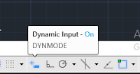
6) Turn OFF the Dynamic Input icon. You will learn about Dynamic Input later in this chapter.
 |
| Dynamic Input Option |
 |
| Icon for point |
on the ribbon,or enter POINT in the command line.
8) Type 50,50 and press ENTER.
9) Type DDPTYPE and press ENTER.

Point Style as per you wish but most probably people prefer + or x style.
Point size - choose Set Size Relative to Screen and enter 5 at Point Size input option.
10) Click Save on the Quick Access Toolbar.
 |
| Save Icon in Quick Access toolbar |
12) Close file.
 |
| Close file |
LINE
You can draw a line by specifying its start point and end point using the Line tool. However, there are various methods to specify start and end of a line. These methods are explained in the following examples.
Example 1 (Using the Absolute Coordinate System)
In this example, you will create lines by specifying points in the absolute coordinate system. In this system, you specify the points with respect to the origin (0,0). A point will be specified by entering its X and Y coordinates separated by a comma.
 |
| Absolute Coordinate System |
2) Click Start Drawing > Templates > acadISO-Named PlotStyles.dwt .
3) Click Zoom > Zoom All on the Navigation Bar.
4) Turn OFF the Grid Display .
5) Turn OFF the Dynamic Input .
6) To draw a point, click Home > Draw >Line
 |
| Line Icon |
7) Type 100,100 and press ENTER . This defines the first point of the line.
8) Type 200,100 and press ENTER .
9) Type 200,150 and press ENTER .
10) Type 100,150 and press ENTER .
11) Select the Close option from the command line.This creates a rectangle as shown below.
 |
| Rectangle by using line tool |
13) Save as Line-Ex1.dwg .
14) Close file.
Example 2 (Using Relative Coordinate system)
In this example, you will draw lines by defining its end points in the relative coordinate system. In the relative coordinate system, you define the location of a point with respect to the previous point.For this purpose the symbol, ‘@’ is used before the point coordinates.This symbol means that the coordinate values are defined in relation with the previous point.
In this example we create same rectangle,which was created by using absolute coordinate in example 1.
1) Start AutoCAD.
2) Click Start Drawing > Templates > acadISO-Named PlotStyles.dwt .
3) Click Zoom > Zoom All on the Navigation Bar.
4) Turn OFF the Grid Display .
5) Turn OFF the Dynamic Input .
6) To draw a point, click Home > Draw >Line on the ribbon,or enter LINE or L in the command line.
7) Type 100,100 and press ENTER . This defines the first point of the line.
8) Type @100,0 and press ENTER .
9) Type @0,50 and press ENTER .
10) Type @-100,0 and press ENTER .
11) Select the Close option from the command line.
12) Save file and close.
Please observe the difference between Absolute coordinate system input values and Relative coordinate system...
Example 3 (Using Polar Coordinate system)
1) Start AutoCAD.
2) Click Start Drawing > Templates > acadISO-Named PlotStyles.dwt .
3) Click Zoom > Zoom All on the Navigation Bar.
4) Turn OFF the Grid Display .
5) Turn OFF the Dynamic Input .
6) To draw a point, click Home > Draw >Line on the ribbon,or enter LINE or L in the command line.
7) Type 100,100 and press ENTER . This defines the first point of the line.
8) Type @100<0 and press ENTER .
9) Type @50<90 and press ENTER.
10) Type @100<180 and press ENTER.
11) Select the Close option from the command line.
12 ) Save file and close.
Example 4 (Using Dynamic Input Mode On)
In this example you will learn drawing objects by using Dynamic Input Mode On, you can draw a line by entering its distance and angle values.
1) Start AutoCAD.
2) Click Start Drawing > Templates > acadISO-Named PlotStyles.dwt .
3) Click Zoom > Zoom All on the Navigation Bar.
4) Turn OFF the Grid Display .
5) Turn ON the Dynamic Input .
6) To draw a point, click Home > Draw >Line on the ribbon,or enter LINE or L in the command line.
7) Type 100,100 and press ENTER . This defines the first point of the line.
8) Move the pointer horizontally toward right and type-in 100 in the length box.
9) Press the TAB key and type 0 as angle. Next, press ENTER.

3) Move the pointer diagonally toward right or left and click to create a rectangle.


2) Click Start Drawing > Templates > acadISO-Named PlotStyles.dwt .
3) Click Zoom > Zoom All on the Navigation Bar.
4) Turn OFF the Grid Display .
5) Turn ON the Dynamic Input .

6) To draw a point, click Home > Draw >Line on the ribbon,or enter LINE or L in the command line.
7) Type 100,100 and press ENTER . This defines the first point of the line.
8) Move the pointer horizontally toward right and type-in 100 in the length box.
9) Press the TAB key and type 0 as angle. Next, press ENTER.

10) Move the pointer vertically upwards and type-in 50 as length.
11) Press the TAB key and type 90 as angle. Next, press ENTER.
12) Move the pointer horizontally toward left and type 100.
13) Press the TAB key and type 180 as angle. Next, press ENTER.
14) Select the Close option from the command line or Move the pointer vertically downwards and type-in 50 as length. Press the TAB key and type 270 as angle. Next, press ENTER.
15) Save file and close.
From the above four examples you learned how to draw an object (in our case Rectangle) by using different coordinate systems and by using Dynamic Input ON and OFF. please master one method to draw objects , my suggestion draw objects by using Dynamic Input ON and use Command line to become more productive.
Erasing, Undoing and Redoing
Though we are in the middle of learning basic drawing tools, i want to teach about three more Modifying tools because they are very useful to draw object by Erasing,Undoing and Redoing objects (If you make any mistake when you are drawing objects).
Draw a random sketch as per your wish using the Line tool.
 |
| Random sketch using line tool |
ERASE
If you want to erase left side lines, shown below by yellow arrows

Click Home > Modify > Erase on the ribbon or Enter ERASE or E in the command line.

Select the lines shown above and press ENTER. This erases the lines.
Click the Undo button on the Quick Access Toolbar. This restores the lines.


Ex 1) Center,Radius method
In this example, you will create a circle by specifying its center and radius value.


Click Home > Modify > Erase on the ribbon or Enter ERASE or E in the command line.

Select the lines shown above and press ENTER. This erases the lines.
Click the Undo button on the Quick Access Toolbar. This restores the lines.
Click the Redo button on the Quick Access Toolbar. This erases the lines again.
Drawing Circles
The tools in the Circle drop-down on the Draw panel can be used to draw circles. You can also type-in the CIRCLE command in the command line and create circles. AutoCAD provides you with six ways to draw an circle.Some these methods are explained in the following examples.
In this example, you will create a circle by specifying its center and radius value.
1) Click Home > Draw >Circle>Center ,Radius on the ribbon.
2) Select an arbitrary point in the graphics window to specify the center point.
3) Type 50 as the radius and press ENTER.
Ex 2) Center,Radius method
In this example, you will create a circle by specifying its center and radius value.
1) Click Home > Draw >Circle>Center ,Diameter on the ribbon.
2) Select an arbitrary point in the graphics window to specify the center point.
3) Type 100 as the diameter and press ENTER.
Try other methods on your own,those are provided in drop-down menu of circle tool...
Drawing Arcs
An arc is a portion of a circle. The total angle of an arc will always be less than 360 degrees. AutoCAD provides you with eleven ways to draw an arc.You can draw arcs in different ways by using the tools available in the Arcs drop-down of the Draw panel. The usage of these tools will depend on your requirement. Some methods to create arcs are explained in the following examples.

Ex 1) 3 Point method
In this example, you will create an arc by specifying three points. The arc will pass through these points.
1) Open Line-Ex1.dwg
2) Turn ON Object snap
3) Click Home > Draw > Arc > 3-Point on the ribbon.
The message, “Specify start point of arc or [Center]:” appears in the command line.
4) Select bottom left corner, top left corner and top right corner.
you can select any 3 corners of rectangle to draw arc or any other three points on your own.

By default the included angle of the arc is measured in the counter-clockwise direction. Press and hold the Ctrl key, if you want to reverse the direction.
2) Pick an arbitrary point in the graphics window to define the start point of an arc.
The message, “Specify center point of arc:” appears.
3) Pick a point to define the radius of the circle. You can also type-in the radius value and press ENTER;

The message, “Specify end point of arc or [Angle/chord Length]:” appears.
In this example, you will create an arc by specifying three points. The arc will pass through these points.
1) Open Line-Ex1.dwg
2) Turn ON Object snap
3) Click Home > Draw > Arc > 3-Point on the ribbon.
The message, “Specify start point of arc or [Center]:” appears in the command line.
4) Select bottom left corner, top left corner and top right corner.
you can select any 3 corners of rectangle to draw arc or any other three points on your own.

Ex 2) Start,Center,End
In this example, you will draw an arc by specifying its start, center and end points. The first two points define the radius of the arc and third point defines its included angle.
1) Click Home > Draw > Arc > Start,Center,End on the ribbon.
The message, “Specify start point of arc or [Center]:” appears in the command line.By default the included angle of the arc is measured in the counter-clockwise direction. Press and hold the Ctrl key, if you want to reverse the direction.
2) Pick an arbitrary point in the graphics window to define the start point of an arc.
The message, “Specify center point of arc:” appears.
3) Pick a point to define the radius of the circle. You can also type-in the radius value and press ENTER;
The message, “Specify end point of arc or [Angle/chord Length]:” appears.
4) Pick a point to define the included angle of the arc. You can also type the angle value and press ENTER.

Drawing Polylines
A Polyline is a single object that consists of line segments and arcs. It is more versatile than a line as you can assign a width to it. In the following example, you will create a closed polyline.
Ex 1)

1) Turn ON Ortho Mode.
2) Click Home > Draw >Polyline on the ribbon,or enter PLINE or PL in the command line.
The message, “Specify start point ” appears in the command line.
3) Select an arbitrary point in the graphics window.
4) Move the pointer horizontally toward right and type 100. Next, press ENTER.
5) Move the pointer vertically upward and type 100. Next, press ENTER.
6) Select the Arc option from the command line.
7) Move the pointer horizontally toward left and type 100. Next, press ENTER.
8) Select the Close option from the command line.
Now, when you select a line segment from the sketch, the whole sketch will be selected. This is because the polyline created is a single object.
Drawing Rectangles
A rectangle is a four sided single object. You can create a rectangle by just specifying its two diagonal corners. However, there are various methods to create a rectangle. Some these methods are explained in the following examples.
Ex 1) In this example, you will create a rectangle by specifying it corner points.
1) Click Home > Draw >Rectangle on the ribbon,or enter RECTANG or REC in the command line.
The message, “Specify corner point or [Chamfer/Elevation/Fillet/Thickness/Width] ” appears in the command line.
2) Pick an arbitrary point in the graphics window.
The message “Specify other corner point or [Area/Dimensions/Rotation]:” appears in the command line.
3) Move the pointer diagonally toward right or left and click to create a rectangle.
Ex 2) In this example, you will create a rectangle by specifying it length and width.

1) Click Home > Draw >Rectangle on the ribbon,or enter RECTANG or REC in the command line.
The message, “Specify corner point or [Chamfer/Elevation/Fillet/Thickness/Width] ” appears in the command line.
2) Pick an arbitrary point in the graphics window.
The message “Specify other corner point or [Area/Dimensions/Rotation]:” appears in the command line.
The message, “Specify corner point or [Chamfer/Elevation/Fillet/Thickness/Width] ” appears in the command line.
2) Pick an arbitrary point in the graphics window.
The message “Specify other corner point or [Area/Dimensions/Rotation]:” appears in the command line.
Select the Dimensions option from the command line.
Specify length for rectangles : Type 500 and press ENTER.
Specify width for rectangles : Type 300 and press ENTER.
Drawing Polygons
A Polygon is a single object having many sides ranging from 3 to 1024. In AutoCAD, you can create regular polygons having sides with equal length. There are two methods to create a polygon. These methods are explained in the following examples.
Ex 1) In this example, you will create a polygon by specifying the number of sides, and then specifying the length of one side.

1) Click Home > Draw >Polygon ( Drop-down menu of Rectangle) on the ribbon,or enter POLYGON or POL in the command line.
The following sequence of messages appears in the command line.
Enter number of sides <4>: Type 5 and press ENTER
Specify center of polygon or [Edge]: Select the Edge option from the command line.
Specify first endpoint of edge: Select an arbitrary point.
Specify second endpoint of edge: Type 300, press TAB and enter angle 30 and press ENTER.
Ex 2) In this example, you will create a polygon by specifying the number of sides, and drawing an imaginary circle (inscribed circle). The polygon will be created with its corners located on the imaginary circle.
You can also create a polygon with the circumscribed circle. A circumscribed circle is an imaginary circle which is tangent to all the sides of a polygon.

1) Click Home > Draw >Polygon on the ribbon,or enter POLYGON or POL in the command line.
The following sequence of messages appears in the command line.
Enter number of sides <4>: Type 6 and press ENTER
Specify center of polygon or [Edge]: Select an arbitrary point.
Enter an option [Inscribed in circle/Circumscribed about circle] <C>: Select the Inscribed in circle option from the command line.
Specify radius of circle: Type 100 and press ENTER,a polygon will be created with its corners touching the imaginary circle.
Drawing Splines
Splines are non-uniform curves, which are used to create irregular shapes. In AutoCAD, you can create splines by using two methods: Spline Fit and Spline CV. These methods are explained in the following examples
Ex 1) Spline Fit
In this example, you will create a spline using the Spline Fit method. In this method you need to specify various points in the graphics window. The spline will be created passing through the specified points.
In this example, you will create a spline using the Spline Fit method. In this method you need to specify various points in the graphics window. The spline will be created passing through the specified points.

1) Expand the Draw panel in the Home tab and select the Spline Fit button.
The message “Specify first point or [Method/Knots/Object]:” appears in the command line.
Copy above Aerofoil data (X,Y cordinates) and Concatenate in Microsoft Excel sheet and copy concatenated data and paste in command line by Right click to produce points in the Graphics window (Try another ways of data import methods in AutoCAD).
2) Join all points with Spline Fit carefully.
3) Press ENTER to create the spline.
Ex 2) Spline CV
In this example, you will create a spline by using the Spline CV method. In this method, you will specify various points called control vertices. As you specify the control vertices, imaginary lines are created connecting them. The spline will be drawn tangent to these lines.
1) Create a polyline, as shown.
2) Expand the Draw panel in the Home tab and select the Spline CV button.

3) Select Object from the command line.
4) Select the polyline and press Enter.

Drawing Ellipses
Ellipses are also non-uniform curves, but they have a regular shape.In AuoCAD, you can draw an ellipse in three different ways by using the tools available in the Ellipse drop-down of the Draw panel. The three different ways to draw ellipses are explained in following examples.
Ex 1) Center
In this example, you will draw an ellipse by specifying three points. The first point defines the center of the ellipse. Second and third points define the two axes of the ellipse.

1) Click Home > Draw > Ellipse > Center on the ribbon.
the message, “Specify center of ellipse:” appears in the command line.
2) Select an arbitrary point in the graphics window.
the message, “Specify endpoint of axis:” appears in the command line.
3) Move the pointer horizontally and type 200. Next, press ENTER.
the message,“Specify distance to other axis or [Rotation]:” appears in the command line.
4) Type 100. and press ENTER; the ellipse will be created.
Ex 2) Axis,End
In this example, you will draw an ellipse by specifying three points. The first two points define the location and length of the first axis. The third point defines the second axis of the ellipse.
1) Dynamic Input ON.
2) Click Home > Draw > Ellipse > Center on the ribbon.
3) Select an arbitrary point to specify an axis endpoint.
4) Type 50 as length of the first axis and press TAB.
5) Type 60 as angle and press ENTER.
6) Type 10 as radius of the second axis and press ENTER; the ellipse will be created inclined at 60 degree angle.
Ex 3) Elliptical Arc
In this example, you will draw an elliptical arc. To draw an elliptical arc, first you need to define the location and length of the first axis. Next,define the radius of the second axis; an ellipse will be displayed. Now, you need to define the start angle of the elliptical arc. The start angle can be any angle between 0 and 360. After defining the start angle, you need to specify the end angle of the elliptical arc.

1) Click Home > Draw > Ellipse > Center on the ribbon.
the message, “Specify axis end point of elliptic arc:” appears in the command line.
2) Select an arbitrary point in the graphics window.
the message, “Specify other end point of axis:” appears in the command line.
3) Move the pointer horizontally towards left and type 300. Next, press ENTER to specify the axis length.
the message, “Specify distance to axis:” appears in the command line.
4) Move the pointer upward and type 100. Next, press ENTER to specify the length of another axis.
the message, “Specify start angle:” appears in the command line.
5) Type 0 and press ENTER to specify the start angle.
the message, “Specify end angle:” appears in the command line.
6) Type 240 and press ENTER to specify the start angle.


Comments
Post a Comment